
A Guideline of Positive Pressure Air Breathing Apparatus
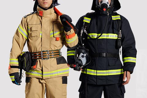
Positive-pressure firefighting air respirator is mainly used for firefighters and rescue personnel to prevent inhalation of poisonous gases, smoke, harmful pollutants suspended in the air, or in the absence of oxygen in firefighting combat or rescue. The respirator cannot be used underwater.
high-pressure
When the respirator is worn and used (the cylinder is upside down with the cylinder valve facing down), the cylinder valve is opened by turning it clockwise and closed by turning it anti-clockwise. The cylinder valve is equipped with a self-locking device, which will not cause the cylinder valve to close due to accidental collision or other reasons during use, avoiding danger and injury to the user and increasing the safety of the respirator.
The safety valve of the cylinder is equipped with a safety diaphragm. when the gas inside the cylinder exceeds the rated working pressure, the safety diaphragm will automatically burst to release the pressure, avoiding the cylinder from bursting, thus protecting the personnel from injury. The burst pressure of the safety diaphragm is 37MPa~45MPa.
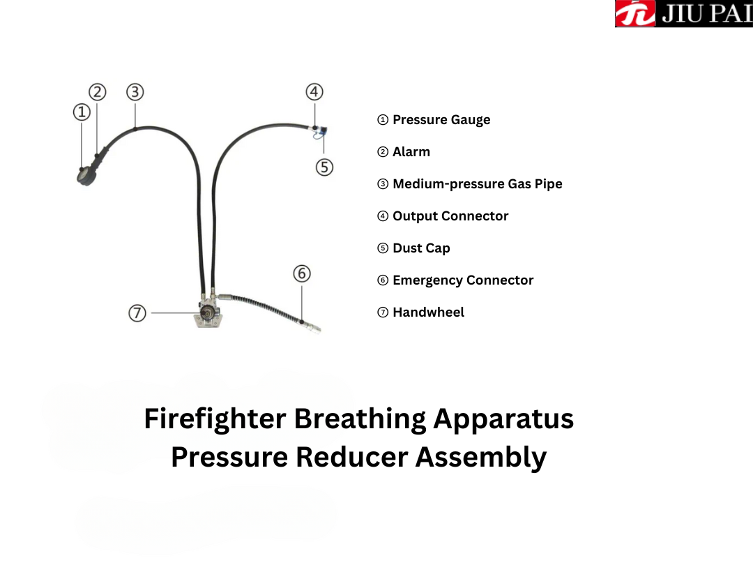
The pressure gauge can easily check the residual pressure inside the bottle and has a luminous display function for easy observation in low light conditions. The pressure gauge has a range of 0~40MPa and is equipped with a rubber protective cover with waterproof and shock-absorbing properties.
The respirator adopts pneumatic alarm, when the cylinder pressure drops to (5.5±0.5)MPa, the alarm will sound a continuous alarm to remind the user to evacuate the operation area as soon as possible. The alarm stops when the cylinder pressure drops below 1MPa. The alarm is a front alarm, which is placed on the user's chest together with the pressure gauge, making it easy for the user to hear the alarm clearly, especially when more than one person is working at the same time, so that they can clearly identify whether the alarm is emitted by their own respirator or not.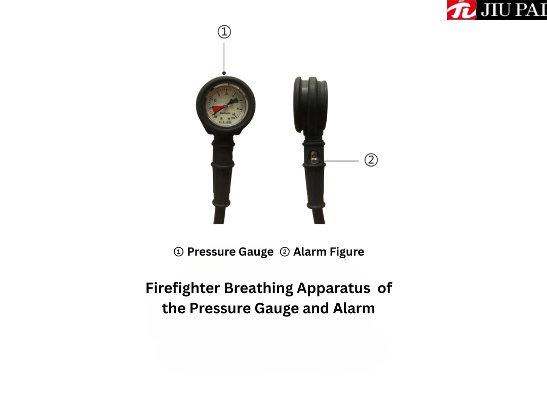
The respirator is fitted with a rescue connector, which is mounted on the pressure reducer and hangs behind the right hand side of the user when the respirator is being worn. Its main function is to ensure that the user has enough air in their own respirator, can carry another pair of other rescue full face mask or full face mask and air supply valve (optional) to the trapped person to supply air rescue.
The medium-pressure conduit is a pressure-resistant rubber hose with an auto-locking quick-connect fitting at the end, which is used to transport air to the air supply valve.
The head net assembly is mainly made of aramid material, thin mesh structure, both left and right sides are equipped with buckle type elasticated straps, which are flexible and can freely adjust the degree of elasticity of the wearer, increasing the convenience and comfort of the wearer.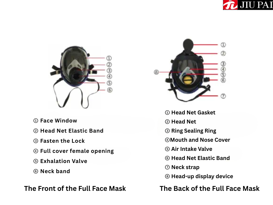 The Combat Full Face Mask is a hemispherical mask with a pressure levelling display device. The mask is a column type three-dimensional structure of one-time casting moulding, face mirror after optical correction, anti-fog anti-scratch coating, three-dimensional type large field of view, medical grade silicone fit face, good sealing, mask suitable for Asian face type, face screen high temperature resistance for 850 degrees, with anti-impact, anti-fog and other functions.
Head Up Display (HUD), hereinafter referred to as HUD, is a display device attached to the firefighting air breathing apparatus mask. This display device uses the colour change of the LED light to display the air pressure of the breathing apparatus cylinder, which is helpful for the firefighters to easily, intuitively and timely understand the change of the air pressure of the cylinder, and provide safer protection measures for the firefighters.
When inhaling, the exhalation valve closes, and the air in the cylinder is inhaled into the human lungs through the cylinder valve, pressure reducer, medium-pressure air conduit, air supply valve, and mouth and nose mask; when exhaling, the air supply valve closes and the exhalation valve opens, and the turbid air is discharged into the ambient atmosphere outside the mask, thus completing a breathing cycle.
Step 2: Check the pressure gauge, cylinder pressure, alarm performance and system air tightness.
①Open the gas supply valve and turn the cylinder valve 2 turns to slowly bleed the gas. Should feel the gas from the gas supply valve in the male outflow, and in the process the alarm should sound a short alarm, that is to indicate that the alarm start normal. This is because when the cylinder just outputs air, the pressure input to the alarm gradually rises from low to high, and the pressure value passes through the alarm interval (5.5MPa±0.5MPa) and causes the alarm.
② face the cylinder, cylinder valve upwards clockwise tighten the cylinder valve, observe the pressure gauge readings, if the pressure value within 1 minute does not exceed 2MPa, and does not continue to decrease, it indicates that the respirator system is airtight and can be used normally.
③ Open the air supply valve and empty the remaining air in the pipeline. Observe the pressure gauge carefully, when the pressure of the cylinder drops to (5.5±0.5)MPa, the alarm should sound continuously again, and the alarm will not stop until the pressure inside the cylinder is less than 1MPa, which indicates that the alarm is working normally.
④ After the air flow has completely stopped, close the air supply valve and remove it from the rig.
Step 3: Check the air tightness of the air supply valve and the mask. Firstly, adjust the neck strap of the full face mask to the loosest possible position and turn the head net to the side of the face window (Figure 6). Close the air supply valve and attach it to the mask. Hold the input connector in your right hand and seal the connector port with your thumb. Next, hold your breath and use your left hand to fit the full face mask over your face snugly and begin a deep inhalation (only inhale and do not exhale at this time). If you hear a clear ‘click’ during the inhalation process, it indicates that the throttle switch of the air supply valve opens normally.
At the same time, when the throttle switch is normally open, if the inhalation process feels that the mouth, nose and mask ring sealing ring to the face tight, the face of the fitting parts of the obvious sense of extrusion, and gradually feel the inhalation tends to stagnation, it shows that the full face mask sealing is good.
Then, loosen the mask from the face and restore the position of the head net. This concludes the pre-use check.
NOTE: It is advisable to use the respirator along with a wireless communication device to ensure that the combatant remains in contact with the backfield command staff at all times to ensure the safety of the combatant.
WARNING: Pre-use inspection of the respirator should ensure that all components of the respirator are up to satisfactory standards before use. If one check is unsuccessful, it is necessary to reconnect the respirator and check it strictly according to the above steps. If the respirator still fails to meet the requirements for use after repeated adjustments, it should be immediately taken out of service and handed over to authorised personnel for overhaul.
The first step is to install the gas cylinder. Firstly, place the back rest flat in the way that the pressure reducer is facing upwards, connect the cylinder filling port with the handwheel of the pressure reducer (if the respirator is equipped with the optional two-part valve of the cylinder, the two-part valve of the cylinder should be installed first), face the handwheel, and tighten the handwheel in the counterclockwise direction when the valve of the cylinder is facing upwards. Then, tighten the cylinder tie to the appropriate position and lock the carabiner.
Step 2, fix the pressure gauge and output connector. Turn the bottom of the cylinder towards you, then unfold the shoulder straps and place them on both sides of the cylinder, fasten the pressure gauge to the Velcro fastener on the left shoulder strap, and fasten the output connector to the fastener on the right shoulder.
Step 3, wear a back brace. Can be used in front of the cross-body type or back throw back wear method, according to the specific circumstances of choice.
Front cross-body type: as the method of backpack.
The user stands at the bottom of the cylinder, grabs the left and right shoulder straps with both hands and lifts them up, puts the right hand and left hand into the straps and hangs them on the shoulders.
Back Throwing Pose (Figure 13, Figure 14, Figure 15): The user stands at the bottom of the cylinder, grasps both sides of the back rest with both hands and lifts the respirator above the head. At the same time, the elbows are tucked in close to the body, and the body is leaning forward slightly, so the respirator naturally slides down the back, and ensures that the shoulder straps are slid down the arms and onto the shoulders.
Step 4: Organise the shoulder straps and waist belt (Figure 16, Figure 17). Adjust the back brace to the proper level of elasticity using the D-rings and belt buckles. It is preferable to wear it comfortably while ensuring that the back wear is secure.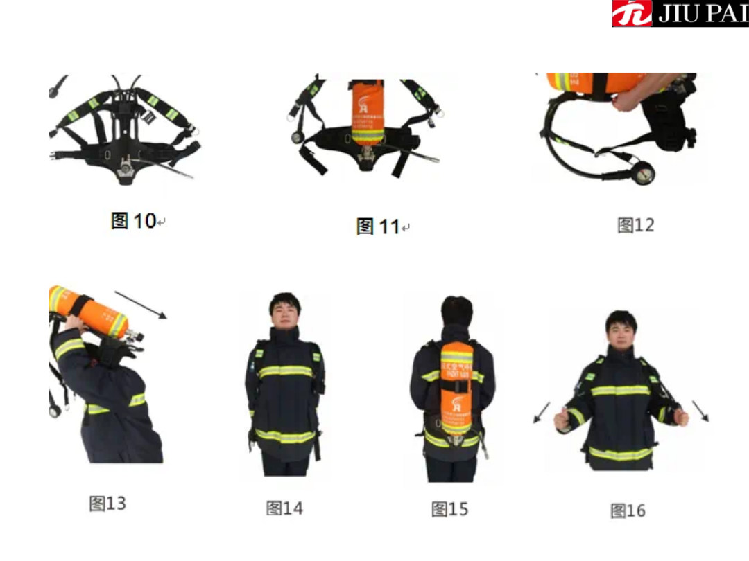
Step 5: Install the air supply valve and hang the full face shield. Firstly, remove the protective film from the face window. Remove the dust cap of the air supply valve and insert the male connector into the female port on the mask (Fig. 18), then gently rotate it back and forth from left to right, and when you hear the ‘click’ sound, it means that the connector of the air supply valve has been slid into the slot on the mask and locked. Afterwards, use the neck strap to hang the mask around your neck. Remove the dust cap of the output connector, connect the air supply valve to the output connector to lock (Fig. 19) and close the air supply valve throttle switch (Fig. 20). At this point, the system is connected and the cylinder valve can be turned on (Figure 21) to allow the cylinder to start supplying air.
Step 6: Wear the full face mask. Adjust the head net elastic to its loosest position and flip the head net up to the side of the face window. With one hand, place the mask over the face, chin and nose into the mouth and nose mask, and adjust the mask to fit snugly over the face. Simultaneously pull the headnet back over the head with the other hand (Fig. 22), the headnet should be smooth and tangle-free. Tighten the headnet by pulling the elasticated headnet strap backward (Fig. 23), and then adjust the elastication of the neck strap. Adjusting the headnet should be done in a way that ensures the airtightness of the mask and is comfortable.
During the wearing of the full facepiece, you should breathe normally in the mask at the right time. The air supply valve's air-saving switch will open automatically and the respirator system will start to supply air. Repeat the breathing several times and you should feel comfortable.
The respirator can only be put into use after it has been checked by the above steps, worn correctly and breathed normally! Otherwise, the respirator should be re-adjusted until it is qualified. Pay attention to the alarm signal from the siren at any time during the use process, and evacuate the site immediately when you hear the alarm sound.
2. Tidy up after use
After the operation is completed, and you are sure that you have left the polluted or unknown air composition environment and are in an environment full of healthy air, you can prepare to unload the respirator.
Firstly, remove the mask from the face by loosening the elasticated head net. Close the cylinder valve and allow the system to empty.
Then, remove the air supply valve input connector from the output connector. Close the air supply valve and remove it from the facepiece.
Finally, unbuckle the waist buckle and loosen the shoulder straps by lifting the D-rings upwards, then remove the respirator from the back of the shoulder and place the back rest flat. Remove the cylinder from the back rest by loosening the cylinder ties, facing the cylinder, and turning the handwheel clockwise when the cylinder valve is facing up. Organise the components of the respirator, close the dust cap and place it properly in the equipment box.
Under the premise of correctly wearing the respirator (Figure 21), the method of opening the cylinder is: clockwise rotation of the cylinder valve, accompanied by a ‘thump'sound of automatic clamping. It should be rotated at least 2 times before the cylinder valve can be completely opened; the method of closing the cylinder is as follows: pinch both sides of the cylinder valve with your hand and push the wheel in the direction of the cylinder, and at the same time rotate the handwheel counterclockwise until the valve is completely unscrewed.
2. Installation and disassembly of quick-connectors
Installation method: the quick-connector has an automatic locking function, insert the input connector into the output connector interface, when you hear a ‘click' sound that indicates that the connector is completely locked.
Disassembly method: the left thumb and forefinger pinch the knurled sleeve of the output connector, the right hand pinches the input connector and pushes it in, the left thumb and forefinger slide back, then the input connector can be pulled out to achieve separation.
3. Installation and removal of gas cylinder
Facing the cylinder, when the cylinder valve is facing up, the correct operation of installing the cylinder is to connect the cylinder filling port with the handwheel of the pressure reducer, and tighten the handwheel clockwise; the correct operation of disassembling is to face the cylinder, when the cylinder valve is facing up, turn the handwheel counterclockwise until the cylinder and the pressure reducer can be completely separated.
Switching off method: Press the red reset button on the air supply valve with your thumb to switch off the throttle switch of the air supply valve.
Installation: Insert the male connector of the valve into the female port of the full facepiece and gently rotate it from side to side, when you hear a ‘click’ sound, the valve is locked.
Removal method: Hold the full face shield with one hand and press the locking buckle, the other hand can pinch the air supply valve to pull it out.
Locking the belt: Insert the male buckle into the female buckle.
Tightening the belt: When tightening the belt, pull the belt to the side and back at the same time with both hands.
Loosening the belt: When the belt is locked, pinch the left and right ends of the belt buckle together with one hand.
Separation of the belt: pinch the upper and lower sides of the belt buckle with one hand, and the male and female buckles will be separated automatically.
Long press the red power button to start the HUD (Figure 25 - power switch), there will be two situations after opening the self-test:
① HUD that has never been paired: the status indicator is flashing rapidly (as Figure 24 - Pairing Indicator This time is looking for the pairing target);
② HUD that has been paired: the status indicator blinks twice continuously (at this time, it is looking for the paired AP or AGP).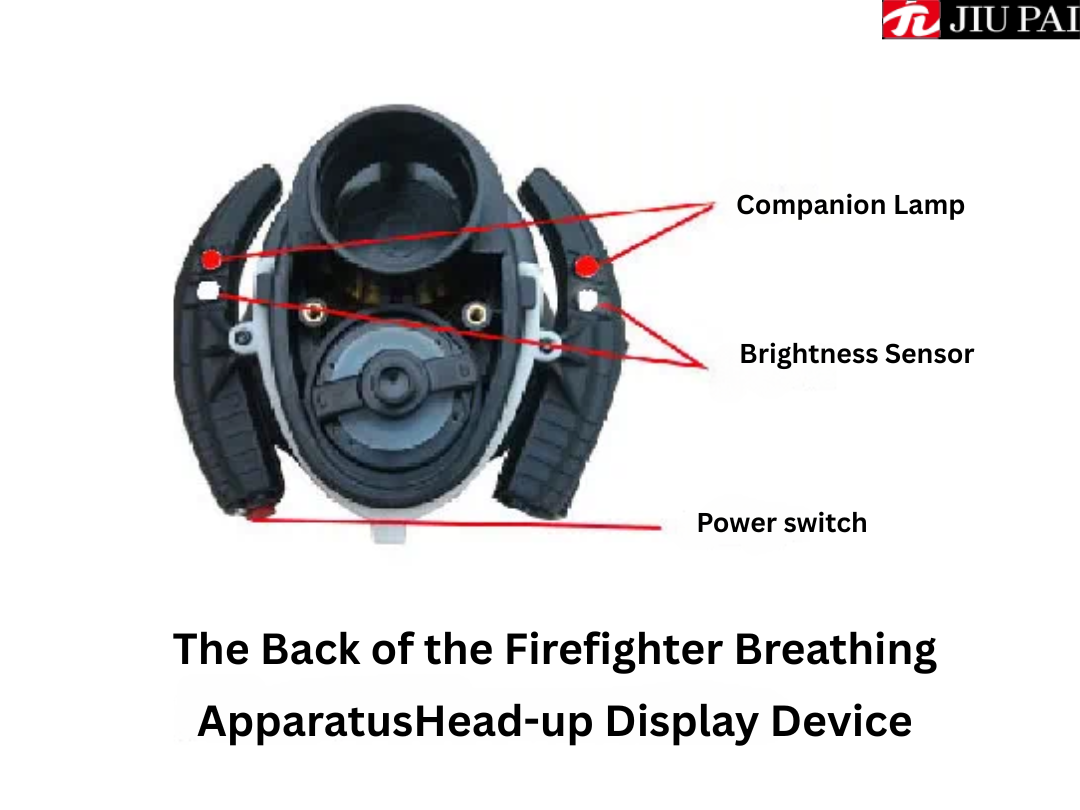 (2) Pairing
If it is AGP-HUD combination, when AGP is on, press and hold MODE button on the upper left corner of AGP until ‘DATA’ blinks on the top of the screen, HUD will be paired with AGP automatically to complete the wireless communication connection.
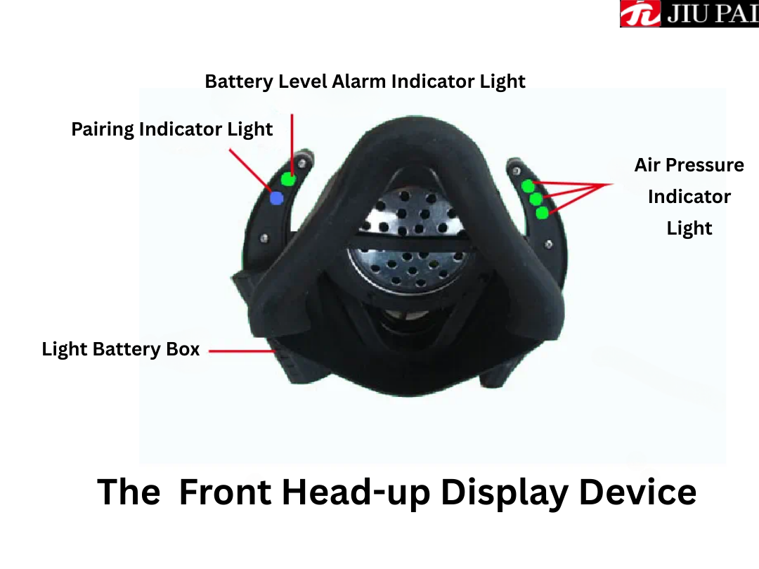
②If it is AP-HUD combination, AP can be switched on directly (load the battery in the battery compartment of AP), HUD will be paired with AP automatically to complete the wireless communication connection. At this time, the power alarm indicator (Figure 24) will show the battery power situation: when the power is sufficient, the indicator shows green; battery power to more than half, the indicator becomes yellow; battery power to use more than 2/3, the indicator becomes red, then we should pay attention to replace the new battery.
(3) Air pressure data transmission
After completing the wireless communication connection, HUD will receive the air pressure information converted to LED light colour for display. When the cylinder air pressure is above 20Mpa, the 3 green lights of the air pressure indicator light up; when the air pressure is 15-20Mpa, the indicator turns into 2 green lights; when the air pressure is 10-15Mpa, the indicator turns into 1 green light; when the air pressure is 5.5-10Mpa, the indicator turns into 1 yellow light; if the air pressure is lower than 5.5Mpa, the indicator turns into 1 red light flashing, and at the same time, the level of If the air pressure is lower than 5.5Mpa, the indicator light will become 1 red light flashing, and 2 partner lights on the back of the display device will flash (Fig. 25), reminding the operator to pay attention to replacing the air cylinder with a new one if the air pressure is insufficient.
 (4) Shutdown
After the ALERT system is finished using, the cylinder air pressure needs to be turned off.
For AGP-HUD combination, turn off AGP first, and HUD will not detect AGP for 40 seconds, then it will shut down automatically.
For the AP-HUD combination, turn off the cylinder air pressure directly, the AP (Figure 26) will automatically hibernate, and the HUD will not detect the AP for 40 seconds, i.e., it will automatically shut down.
A long press on the power button at any time while the unit is on will also cause the HUD to manually shut down.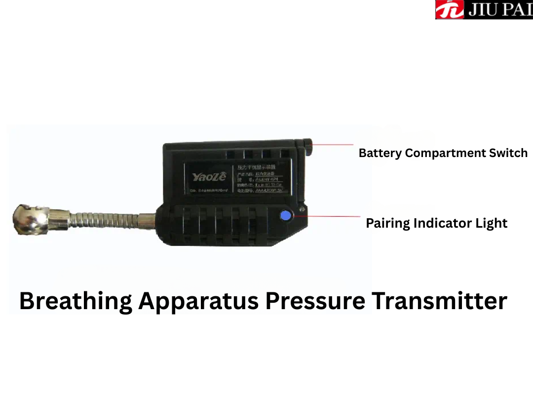
2. The permissible temperature range of the respirator is -30℃~60℃, and it shall not be used as a diving respirator!
3. The respirator must be carefully checked before use in strict accordance with the inspection procedures, it is strictly prohibited to use the respirator without complete inspection or unqualified inspection for operation, otherwise all the responsibility is borne by the user himself.
4. It is not allowed to fill any other kind of gas in the high-pressure cylinder, otherwise, explosion may occur.
5. This respirator is not permitted to be worn when the user's facial conditions prevent a good seal between the face and the mask, such as whiskers, sideburns or spectacle frames.
6. The rescue connector of the respirator should only be used when rescuing another person in an emergency, and the output connector is used by default unless otherwise specified herein. Do not connect the air supply valve to the other rescue connector to check the air tightness of the system.
7. The respirator should be used to ensure that the cylinder valve is fully open, and to avoid collision of the cylinder. Users should always check the cylinder pressure gauge, once the pressure pointer drops rapidly, the alarm sounds, or feel the increase of breathing resistance, breathing difficulties, dizziness and other discomforts, as well as other abnormal phenomena, should be promptly evacuated from the scene.
8. The pressure of the cylinder shall not exceed 30MPa when it is inflated, and the gas inside the cylinder shall not be completely emptied after use, and the air pressure of at least 0.2MPa shall be maintained to prevent dust or air containing impurities from entering into the cylinder.
9. Non-authorised personnel shall not dismantle parts of the respirator without authorisation, such as pressure reducer, safety valve and alarm. When disassembling the quick-connect coupling or carrying out maintenance, the gas cylinder should be shut down first and should not be operated under pressure.
10. Avoid exposing the high-pressure cylinder to high temperatures, especially direct sunlight. Prohibit staining any grease.
1. visually inspect the complete respirator for worn or deteriorated rubber parts, frayed or loose webbing and damaged parts.
2. Check the most recent pressure test date of the cylinder to confirm that the cylinder is within its valid service life. If it has exceeded the expiry date, stop using the cylinder immediately, mark it and have an authorised person carry out a pressure test and pass the test before it can be used again.
3. Check whether there is any physical damage on the cylinder, such as dents, bumps, scratches or cracks, etc.; whether there is any heat damage caused by high temperature or over-fire to the cylinder, such as paint turning brown or black, burnt or disappeared characters, melted or damaged pressure dials; and whether there is any traces of chemical damage caused by acid or other corrosive chemicals, such as peeling off of the outer layer of the winding, etc. If any of the above conditions is found, it should be stopped and marked by the authorised personnel before using. If any of the above conditions are found, the cylinder should no longer be used and the compressed air in the cylinder should be completely bled off and marked to await disposal by authorised personnel.
4. Check whether the cylinder is full (the pressure gauge shows 28MPa ~ 30MPa when the cylinder is full). If the cylinder is not full, replace it with a cylinder full of compressed air.
5. Check whether the handwheel of the pressure reducer can be tightened with the cylinder valve filling port. When closing the cylinder valve, do not rotate the handwheel violently, otherwise it may lead to the damage of the cylinder valve gasket and affect the sealing performance of the cylinder valve.
1. Check the respirator for worn or aged rubber parts, worn or loose hood webbing or damaged parts.
2. Clean and disinfect the full facepiece. Add neutral soap solution or detergent to warm water (maximum temperature 43°C) and scrub the surface of the mask using a soft cotton cloth. Use a sponge dipped in medical alcohol to disinfect key parts such as the face window and ring seal. After disinfection, dry with a clean soft cloth or blow dry gently with clean and dry air at a pressure of less than 0.2MPa. Residual detergent or disinfectant on mask components that have not been thoroughly washed and completely dried can cause damage to mask parts.
3. Clean and disinfect the air supply valve. Use a sponge or soft cloth to wipe off any visible dirt from the outer surface of the air supply valve. Check the inside of the air supply valve through the air outlet of the air supply valve. If it has become dirty, have it cleaned by authorised personnel.
4. If the air supply valve requires cleaning, switch off the throttle switch and scrub the air supply valve connection with medical alcohol. Then shake the valve to remove any residual water. Flush the valve with drinking water. Rinse under gently running water. Do not immerse the valve directly in the solution or in water. Shake the air supply valve to remove residual water and blow it thoroughly with air at a pressure of not more than 0.2 MPa. Periodically applying a small amount of silicone grease evenly to the sealing gasket of the air supply valve will make it easier to fit the valve onto the mask.
5. Use a damp sponge or soft cloth to scrub other parts of the respirator that cannot be immersed in water for cleaning.
Warning: In the process of cleaning and disinfecting the respirator, do not infiltrate water into the medium pressure air guide tube and alarm device, otherwise it will easily cause equipment failure, affect the service life of the respirator, and may even cause potential safety hazards.
If the respirator is suspected of being contaminated by hazardous materials during use, the contaminated area must be marked and handed over to authorised personnel for disposal.
2. When respirators and their spare parts are to be transported by means of a vehicle, they shall be secured in storage by reliable mechanical means or stored in equipment cases suitable for the transport and storage of respirators and their spare parts. During transport, respirators should be packed and stored in such a way as to avoid injury to the vehicle or to persons in the vicinity due to acceleration and deceleration of the vehicle, sharp turns, or in the event of an accident. When respirators are transported as general cargo, the cylinders shall be empty. If transported in a gassed state, they shall comply with the regulations of the transport authorities.
Structure of Positive Pressure Air Breathing Apparatus
The respirator consists of five parts: cylinder assembly, pressure reducer assembly, full facepiece assembly, air supply valve assembly, and back support assembly, and is equipped with a tool kit, storage bag, and equipment box.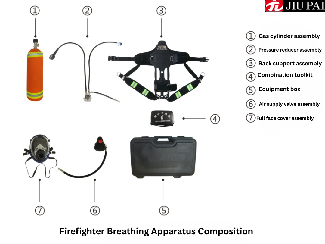
Cylinder Assembly
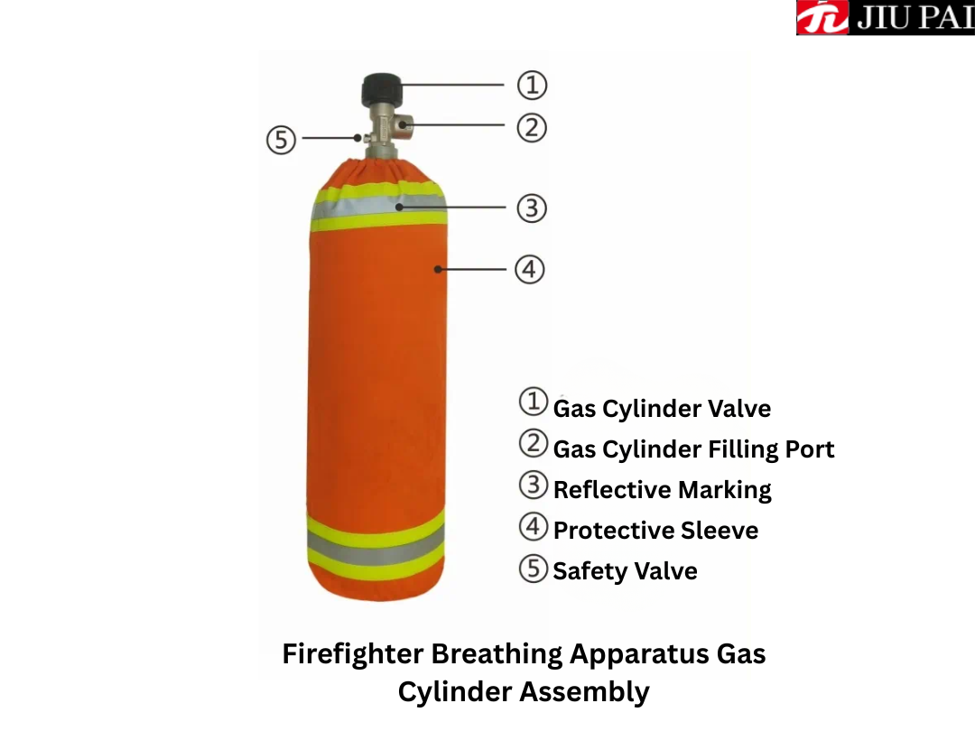
The cylinder assembly is a device used to store high pressure compressed air. The cylinder is made of carbon fibre composite material, with a rated working pressure is 30MPa, a volume is 6.8L (9L), the thread of the head valve interface is G5/8, equipped with a fast filling structure. The cylinder has the advantages of light weight, corrosion resistance, high strength, good safety performance, long service life, etc., which enables the wearer to reduce the physical exertion during the respirator operation.high-pressure
When the respirator is worn and used (the cylinder is upside down with the cylinder valve facing down), the cylinder valve is opened by turning it clockwise and closed by turning it anti-clockwise. The cylinder valve is equipped with a self-locking device, which will not cause the cylinder valve to close due to accidental collision or other reasons during use, avoiding danger and injury to the user and increasing the safety of the respirator.
The safety valve of the cylinder is equipped with a safety diaphragm. when the gas inside the cylinder exceeds the rated working pressure, the safety diaphragm will automatically burst to release the pressure, avoiding the cylinder from bursting, thus protecting the personnel from injury. The burst pressure of the safety diaphragm is 37MPa~45MPa.
Reducer Assembly
Pressure reducer assembly is a gas cylinder for high-pressure gas decompression, an output of about 0.8MPa medium-pressure gas, through the medium-pressure conduit to the gas supply valve for the user to breathe the device. The pressure reducer can work normally within the temperature of -40℃~+80℃. Pressure reducer assembly consists of pressure reducer, handwheel, pressure gauge, alarm, medium pressure gas conduit, output connector and another rescue connector.The pressure gauge can easily check the residual pressure inside the bottle and has a luminous display function for easy observation in low light conditions. The pressure gauge has a range of 0~40MPa and is equipped with a rubber protective cover with waterproof and shock-absorbing properties.
The respirator adopts pneumatic alarm, when the cylinder pressure drops to (5.5±0.5)MPa, the alarm will sound a continuous alarm to remind the user to evacuate the operation area as soon as possible. The alarm stops when the cylinder pressure drops below 1MPa. The alarm is a front alarm, which is placed on the user's chest together with the pressure gauge, making it easy for the user to hear the alarm clearly, especially when more than one person is working at the same time, so that they can clearly identify whether the alarm is emitted by their own respirator or not.
The respirator is fitted with a rescue connector, which is mounted on the pressure reducer and hangs behind the right hand side of the user when the respirator is being worn. Its main function is to ensure that the user has enough air in their own respirator, can carry another pair of other rescue full face mask or full face mask and air supply valve (optional) to the trapped person to supply air rescue.
The medium-pressure conduit is a pressure-resistant rubber hose with an auto-locking quick-connect fitting at the end, which is used to transport air to the air supply valve.
Full-cover Assembly
Full face mask assembly (Figure 5, Figure 6) is used to cover the face, isolate toxic and harmful gases and prevent them from entering the human respiratory system. The mask assembly mainly consists of a large field of view face window, mouth and nose mask, exhalation valve, mask female mouth, pressure level display device and head net components. The mouth and nose shield inside the face window can completely cover the mouth and nose of the wearer, which can effectively improve the air utilisation rate.The head net assembly is mainly made of aramid material, thin mesh structure, both left and right sides are equipped with buckle type elasticated straps, which are flexible and can freely adjust the degree of elasticity of the wearer, increasing the convenience and comfort of the wearer.
Head Up Display (HUD), hereinafter referred to as HUD, is a display device attached to the firefighting air breathing apparatus mask. This display device uses the colour change of the LED light to display the air pressure of the breathing apparatus cylinder, which is helpful for the firefighters to easily, intuitively and timely understand the change of the air pressure of the cylinder, and provide safer protection measures for the firefighters.
Air Supply Valve Assembly
The air supply valve assembly is a device that decompresses the medium-pressure gas output from the pressure reducer to the pressure at which the human body can breathe, and provides the user with the required air. The air supply valve can automatically adjust the valve opening volume according to the wearer's breathing volume, and the air supply valve is equipped with an automatic positive pressure mechanism, which ensures that the wearer is under positive pressure inside the mask during the working process, regardless of inhalation or exhalation. The air supply valve assembly is directly mounted on the female port of the mask through the male connector, and the other end of the air supply valve is the input connector, which can be connected to the output connector of the medium-pressure air conduit. The part of the air supply valve protected by rubber is the throttle switch, and the red button is the throttle switch reset button. When the mask is removed from the face, pressing the red button closes the air supply valve, at which point the air supply stops. When the system is connected and the cylinder is switched on, and the full facepiece is worn over the face to maintain the seal and inhale, the throttle switch will automatically switch on with a crisp ‘click’ sound, and the system will be switched on and air supply will begin. The flow rate of the air supply valve is more than 450L/min, and the connection between the medium pressure tube and the air supply valve is movable (360°rotatable).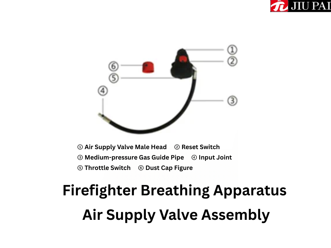
Back Rest Assembly
The back support assembly is a device used to support the cylinder assembly and the pressure reducer assembly. The back support assembly mainly consists of a high-strength plastic back frame, a left shoulder strap, a right shoulder strap, a waist belt and a gas cylinder tie. The main back frame adopts ergonomic design, so as to keep the whole set of equipment and the human body to wear well, both coordinated and comfortable. The main function is to measure the air pressure of the respirator cylinder by means of a pressure sensor and convert it into a standard electrical signal, which is then transmitted to the pressure levelling device in the full facepiece via wireless communication. The back frame and straps are flame retardant, waterproof, anti-static, impact resistant, acid corrosion resistant, and can be used at temperatures ranging from -40°C to +140°C or higher. There is a buckle on the cylinder strap for quick locking of the cylinder; the belt is equipped with a belt buckle for tightening and separating the belt and adjusting the elasticity of the belt.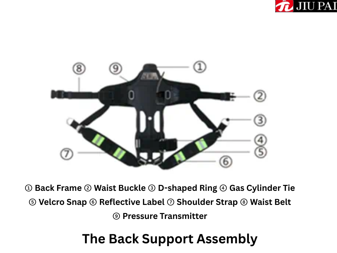
Working Principle
The respirator components are connected correctly, when the cylinder valve is opened, the high-pressure air stored in the cylinder enters the pressure reducer assembly through the cylinder valve, and the high-pressure air outputs the medium-pressure air of about 0.8MPa after decompression, meanwhile, the pressure gauge displays the real-time value of the pressure of the air in the medium-pressure air-conducting tube. The medium-pressure air enters the air supply valve installed on the mask through the medium-pressure air guide tube, and the air supply valve provides the required air according to the user's inhalation requirement, and always keeps the mask in a positive pressure state.When inhaling, the exhalation valve closes, and the air in the cylinder is inhaled into the human lungs through the cylinder valve, pressure reducer, medium-pressure air conduit, air supply valve, and mouth and nose mask; when exhaling, the air supply valve closes and the exhalation valve opens, and the turbid air is discharged into the ambient atmosphere outside the mask, thus completing a breathing cycle.
Usage of Positive Pressure Air Breathing Apparatus
Check Before Use
Step 1: Open the box and check the completeness of the equipment. Firstly, place the respirator box on the ground, open the lid and remove all components of the respirator. According to the packing list, check one by one to ensure that the respirator is fully equipped with all components, the surface of the equipment is clean, the pipeline is free of kinks and damages, the connection parts are secure, and all components should be kept intact and in good working order. Then, lay the back rest flat with the pressure reducer facing upwards, install the cylinder, fasten the cylinder tie, and connect the air supply valve to the output connector.Step 2: Check the pressure gauge, cylinder pressure, alarm performance and system air tightness.
①Open the gas supply valve and turn the cylinder valve 2 turns to slowly bleed the gas. Should feel the gas from the gas supply valve in the male outflow, and in the process the alarm should sound a short alarm, that is to indicate that the alarm start normal. This is because when the cylinder just outputs air, the pressure input to the alarm gradually rises from low to high, and the pressure value passes through the alarm interval (5.5MPa±0.5MPa) and causes the alarm.
② face the cylinder, cylinder valve upwards clockwise tighten the cylinder valve, observe the pressure gauge readings, if the pressure value within 1 minute does not exceed 2MPa, and does not continue to decrease, it indicates that the respirator system is airtight and can be used normally.
③ Open the air supply valve and empty the remaining air in the pipeline. Observe the pressure gauge carefully, when the pressure of the cylinder drops to (5.5±0.5)MPa, the alarm should sound continuously again, and the alarm will not stop until the pressure inside the cylinder is less than 1MPa, which indicates that the alarm is working normally.
④ After the air flow has completely stopped, close the air supply valve and remove it from the rig.
Step 3: Check the air tightness of the air supply valve and the mask. Firstly, adjust the neck strap of the full face mask to the loosest possible position and turn the head net to the side of the face window (Figure 6). Close the air supply valve and attach it to the mask. Hold the input connector in your right hand and seal the connector port with your thumb. Next, hold your breath and use your left hand to fit the full face mask over your face snugly and begin a deep inhalation (only inhale and do not exhale at this time). If you hear a clear ‘click’ during the inhalation process, it indicates that the throttle switch of the air supply valve opens normally.
At the same time, when the throttle switch is normally open, if the inhalation process feels that the mouth, nose and mask ring sealing ring to the face tight, the face of the fitting parts of the obvious sense of extrusion, and gradually feel the inhalation tends to stagnation, it shows that the full face mask sealing is good.
Then, loosen the mask from the face and restore the position of the head net. This concludes the pre-use check.
NOTE: It is advisable to use the respirator along with a wireless communication device to ensure that the combatant remains in contact with the backfield command staff at all times to ensure the safety of the combatant.
WARNING: Pre-use inspection of the respirator should ensure that all components of the respirator are up to satisfactory standards before use. If one check is unsuccessful, it is necessary to reconnect the respirator and check it strictly according to the above steps. If the respirator still fails to meet the requirements for use after repeated adjustments, it should be immediately taken out of service and handed over to authorised personnel for overhaul.
Correct Ways to Wear Respirator Operation Steps
WARNING: The user should receive professional training before using this respirator and be qualified by examination before wearing it for operation. During the use, you must ensure that the cylinder valve is always in a safe and open state.The first step is to install the gas cylinder. Firstly, place the back rest flat in the way that the pressure reducer is facing upwards, connect the cylinder filling port with the handwheel of the pressure reducer (if the respirator is equipped with the optional two-part valve of the cylinder, the two-part valve of the cylinder should be installed first), face the handwheel, and tighten the handwheel in the counterclockwise direction when the valve of the cylinder is facing upwards. Then, tighten the cylinder tie to the appropriate position and lock the carabiner.
Step 2, fix the pressure gauge and output connector. Turn the bottom of the cylinder towards you, then unfold the shoulder straps and place them on both sides of the cylinder, fasten the pressure gauge to the Velcro fastener on the left shoulder strap, and fasten the output connector to the fastener on the right shoulder.
Step 3, wear a back brace. Can be used in front of the cross-body type or back throw back wear method, according to the specific circumstances of choice.
Front cross-body type: as the method of backpack.
The user stands at the bottom of the cylinder, grabs the left and right shoulder straps with both hands and lifts them up, puts the right hand and left hand into the straps and hangs them on the shoulders.
Back Throwing Pose (Figure 13, Figure 14, Figure 15): The user stands at the bottom of the cylinder, grasps both sides of the back rest with both hands and lifts the respirator above the head. At the same time, the elbows are tucked in close to the body, and the body is leaning forward slightly, so the respirator naturally slides down the back, and ensures that the shoulder straps are slid down the arms and onto the shoulders.
Step 4: Organise the shoulder straps and waist belt (Figure 16, Figure 17). Adjust the back brace to the proper level of elasticity using the D-rings and belt buckles. It is preferable to wear it comfortably while ensuring that the back wear is secure.
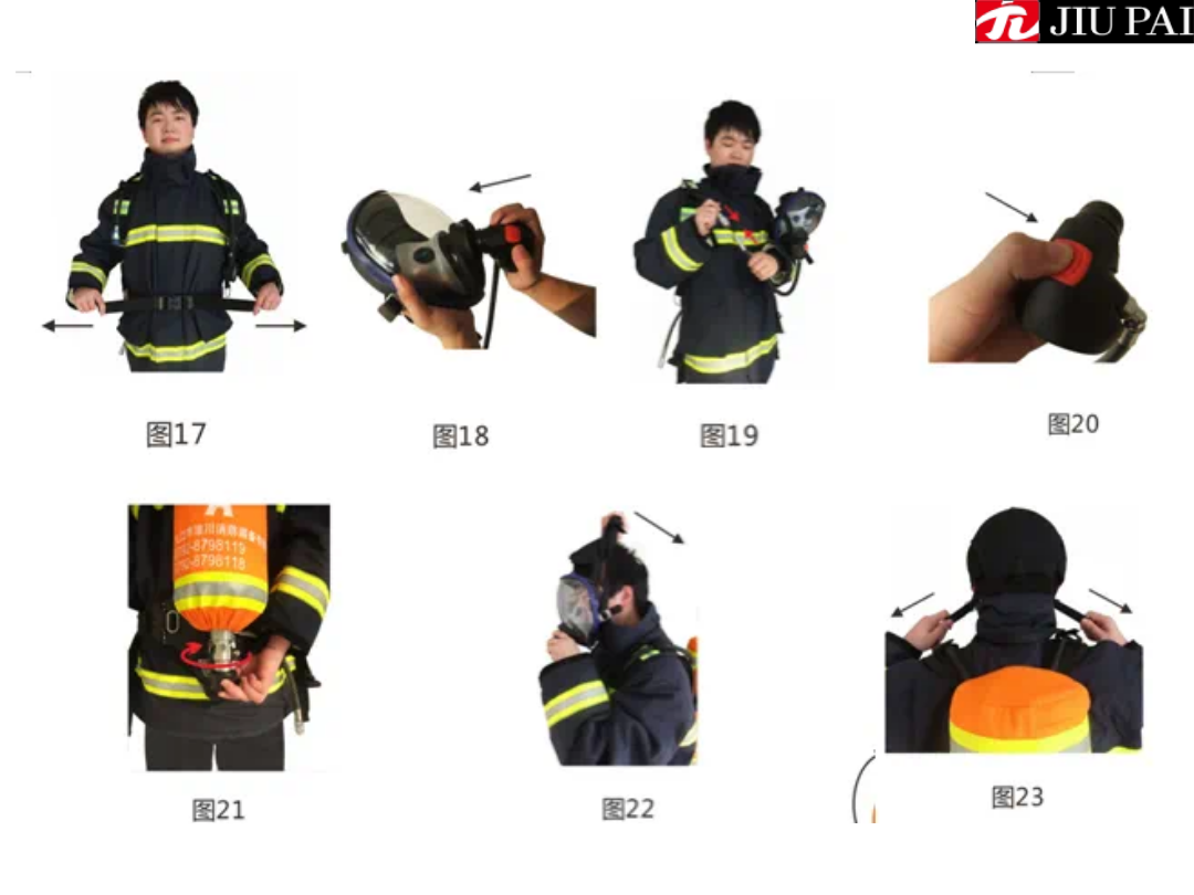
Step 5: Install the air supply valve and hang the full face shield. Firstly, remove the protective film from the face window. Remove the dust cap of the air supply valve and insert the male connector into the female port on the mask (Fig. 18), then gently rotate it back and forth from left to right, and when you hear the ‘click’ sound, it means that the connector of the air supply valve has been slid into the slot on the mask and locked. Afterwards, use the neck strap to hang the mask around your neck. Remove the dust cap of the output connector, connect the air supply valve to the output connector to lock (Fig. 19) and close the air supply valve throttle switch (Fig. 20). At this point, the system is connected and the cylinder valve can be turned on (Figure 21) to allow the cylinder to start supplying air.
Step 6: Wear the full face mask. Adjust the head net elastic to its loosest position and flip the head net up to the side of the face window. With one hand, place the mask over the face, chin and nose into the mouth and nose mask, and adjust the mask to fit snugly over the face. Simultaneously pull the headnet back over the head with the other hand (Fig. 22), the headnet should be smooth and tangle-free. Tighten the headnet by pulling the elasticated headnet strap backward (Fig. 23), and then adjust the elastication of the neck strap. Adjusting the headnet should be done in a way that ensures the airtightness of the mask and is comfortable.
During the wearing of the full facepiece, you should breathe normally in the mask at the right time. The air supply valve's air-saving switch will open automatically and the respirator system will start to supply air. Repeat the breathing several times and you should feel comfortable.
The respirator can only be put into use after it has been checked by the above steps, worn correctly and breathed normally! Otherwise, the respirator should be re-adjusted until it is qualified. Pay attention to the alarm signal from the siren at any time during the use process, and evacuate the site immediately when you hear the alarm sound.
2. Tidy up after use
After the operation is completed, and you are sure that you have left the polluted or unknown air composition environment and are in an environment full of healthy air, you can prepare to unload the respirator.
Firstly, remove the mask from the face by loosening the elasticated head net. Close the cylinder valve and allow the system to empty.
Then, remove the air supply valve input connector from the output connector. Close the air supply valve and remove it from the facepiece.
Finally, unbuckle the waist buckle and loosen the shoulder straps by lifting the D-rings upwards, then remove the respirator from the back of the shoulder and place the back rest flat. Remove the cylinder from the back rest by loosening the cylinder ties, facing the cylinder, and turning the handwheel clockwise when the cylinder valve is facing up. Organise the components of the respirator, close the dust cap and place it properly in the equipment box.
Operating Techniques
1. Cylinder valve opening and closing methodUnder the premise of correctly wearing the respirator (Figure 21), the method of opening the cylinder is: clockwise rotation of the cylinder valve, accompanied by a ‘thump'sound of automatic clamping. It should be rotated at least 2 times before the cylinder valve can be completely opened; the method of closing the cylinder is as follows: pinch both sides of the cylinder valve with your hand and push the wheel in the direction of the cylinder, and at the same time rotate the handwheel counterclockwise until the valve is completely unscrewed.
2. Installation and disassembly of quick-connectors
Installation method: the quick-connector has an automatic locking function, insert the input connector into the output connector interface, when you hear a ‘click' sound that indicates that the connector is completely locked.
Disassembly method: the left thumb and forefinger pinch the knurled sleeve of the output connector, the right hand pinches the input connector and pushes it in, the left thumb and forefinger slide back, then the input connector can be pulled out to achieve separation.
3. Installation and removal of gas cylinder
Facing the cylinder, when the cylinder valve is facing up, the correct operation of installing the cylinder is to connect the cylinder filling port with the handwheel of the pressure reducer, and tighten the handwheel clockwise; the correct operation of disassembling is to face the cylinder, when the cylinder valve is facing up, turn the handwheel counterclockwise until the cylinder and the pressure reducer can be completely separated.
How to Use the Air Supply Valve
Opening method: when you need to open manually, press the throttle switch with your thumb, accompanied by a ‘thump’ sound that indicates that it has been opened; the air supply valve is equipped with an automatic opening function, when the system is fully connected to the gas cylinder supply is normal, and the full-face mask is worn correctly, the throttle switch in the closed state will be turned on automatically when the wearer begins to inhale.Switching off method: Press the red reset button on the air supply valve with your thumb to switch off the throttle switch of the air supply valve.
Installation: Insert the male connector of the valve into the female port of the full facepiece and gently rotate it from side to side, when you hear a ‘click’ sound, the valve is locked.
Removal method: Hold the full face shield with one hand and press the locking buckle, the other hand can pinch the air supply valve to pull it out.
Adjustment of Shoulder Straps and Waist Belt
Loosening of the shoulder belt: Hook your thumb on the D-ring and lift it upwards gently, then the shoulder belt will automatically loosen backward.Locking the belt: Insert the male buckle into the female buckle.
Tightening the belt: When tightening the belt, pull the belt to the side and back at the same time with both hands.
Loosening the belt: When the belt is locked, pinch the left and right ends of the belt buckle together with one hand.
Separation of the belt: pinch the upper and lower sides of the belt buckle with one hand, and the male and female buckles will be separated automatically.
How to use the Pressure Level Display Device
(1) Switch onLong press the red power button to start the HUD (Figure 25 - power switch), there will be two situations after opening the self-test:
① HUD that has never been paired: the status indicator is flashing rapidly (as Figure 24 - Pairing Indicator This time is looking for the pairing target);
② HUD that has been paired: the status indicator blinks twice continuously (at this time, it is looking for the paired AP or AGP).
If it is AGP-HUD combination, when AGP is on, press and hold MODE button on the upper left corner of AGP until ‘DATA’ blinks on the top of the screen, HUD will be paired with AGP automatically to complete the wireless communication connection.
②If it is AP-HUD combination, AP can be switched on directly (load the battery in the battery compartment of AP), HUD will be paired with AP automatically to complete the wireless communication connection. At this time, the power alarm indicator (Figure 24) will show the battery power situation: when the power is sufficient, the indicator shows green; battery power to more than half, the indicator becomes yellow; battery power to use more than 2/3, the indicator becomes red, then we should pay attention to replace the new battery.
(3) Air pressure data transmission
After completing the wireless communication connection, HUD will receive the air pressure information converted to LED light colour for display. When the cylinder air pressure is above 20Mpa, the 3 green lights of the air pressure indicator light up; when the air pressure is 15-20Mpa, the indicator turns into 2 green lights; when the air pressure is 10-15Mpa, the indicator turns into 1 green light; when the air pressure is 5.5-10Mpa, the indicator turns into 1 yellow light; if the air pressure is lower than 5.5Mpa, the indicator turns into 1 red light flashing, and at the same time, the level of If the air pressure is lower than 5.5Mpa, the indicator light will become 1 red light flashing, and 2 partner lights on the back of the display device will flash (Fig. 25), reminding the operator to pay attention to replacing the air cylinder with a new one if the air pressure is insufficient.
After the ALERT system is finished using, the cylinder air pressure needs to be turned off.
For AGP-HUD combination, turn off AGP first, and HUD will not detect AGP for 40 seconds, then it will shut down automatically.
For the AP-HUD combination, turn off the cylinder air pressure directly, the AP (Figure 26) will automatically hibernate, and the HUD will not detect the AP for 40 seconds, i.e., it will automatically shut down.
A long press on the power button at any time while the unit is on will also cause the HUD to manually shut down.
Precautions
1. Before using the product should carefully read the instruction manual, do not follow the instructions will likely cause serious consequences.2. The permissible temperature range of the respirator is -30℃~60℃, and it shall not be used as a diving respirator!
3. The respirator must be carefully checked before use in strict accordance with the inspection procedures, it is strictly prohibited to use the respirator without complete inspection or unqualified inspection for operation, otherwise all the responsibility is borne by the user himself.
4. It is not allowed to fill any other kind of gas in the high-pressure cylinder, otherwise, explosion may occur.
5. This respirator is not permitted to be worn when the user's facial conditions prevent a good seal between the face and the mask, such as whiskers, sideburns or spectacle frames.
6. The rescue connector of the respirator should only be used when rescuing another person in an emergency, and the output connector is used by default unless otherwise specified herein. Do not connect the air supply valve to the other rescue connector to check the air tightness of the system.
7. The respirator should be used to ensure that the cylinder valve is fully open, and to avoid collision of the cylinder. Users should always check the cylinder pressure gauge, once the pressure pointer drops rapidly, the alarm sounds, or feel the increase of breathing resistance, breathing difficulties, dizziness and other discomforts, as well as other abnormal phenomena, should be promptly evacuated from the scene.
8. The pressure of the cylinder shall not exceed 30MPa when it is inflated, and the gas inside the cylinder shall not be completely emptied after use, and the air pressure of at least 0.2MPa shall be maintained to prevent dust or air containing impurities from entering into the cylinder.
9. Non-authorised personnel shall not dismantle parts of the respirator without authorisation, such as pressure reducer, safety valve and alarm. When disassembling the quick-connect coupling or carrying out maintenance, the gas cylinder should be shut down first and should not be operated under pressure.
10. Avoid exposing the high-pressure cylinder to high temperatures, especially direct sunlight. Prohibit staining any grease.
Maintenance
Regular Inspection
Spare respirators must be inspected weekly or at a frequency that ensures that the respirator will function properly when it is required for use. The pressure gauge should be calibrated and checked once a year, and the high pressure cylinder and cylinder valve should be re-inspected every three years. If any malfunction is found, it must be separated from the normal respirator and marked so that it can be repaired by an authorised person.1. visually inspect the complete respirator for worn or deteriorated rubber parts, frayed or loose webbing and damaged parts.
2. Check the most recent pressure test date of the cylinder to confirm that the cylinder is within its valid service life. If it has exceeded the expiry date, stop using the cylinder immediately, mark it and have an authorised person carry out a pressure test and pass the test before it can be used again.
3. Check whether there is any physical damage on the cylinder, such as dents, bumps, scratches or cracks, etc.; whether there is any heat damage caused by high temperature or over-fire to the cylinder, such as paint turning brown or black, burnt or disappeared characters, melted or damaged pressure dials; and whether there is any traces of chemical damage caused by acid or other corrosive chemicals, such as peeling off of the outer layer of the winding, etc. If any of the above conditions is found, it should be stopped and marked by the authorised personnel before using. If any of the above conditions are found, the cylinder should no longer be used and the compressed air in the cylinder should be completely bled off and marked to await disposal by authorised personnel.
4. Check whether the cylinder is full (the pressure gauge shows 28MPa ~ 30MPa when the cylinder is full). If the cylinder is not full, replace it with a cylinder full of compressed air.
5. Check whether the handwheel of the pressure reducer can be tightened with the cylinder valve filling port. When closing the cylinder valve, do not rotate the handwheel violently, otherwise it may lead to the damage of the cylinder valve gasket and affect the sealing performance of the cylinder valve.
Periodic Testing
The respirator should be visually inspected and performance tested by authorised personnel at least once a year. However, if the respirator is used frequently or under severe conditions, the periodic testing interval should be shortened. Cylinders used in conjunction with the respirator must pass the periodic inspection and evaluation conducted by the inspection agency authorised by the State Bureau of Quality and Technical Supervision.Cleaning and Maintenance
Clean and maintain the respirator according to the following steps after each use:1. Check the respirator for worn or aged rubber parts, worn or loose hood webbing or damaged parts.
2. Clean and disinfect the full facepiece. Add neutral soap solution or detergent to warm water (maximum temperature 43°C) and scrub the surface of the mask using a soft cotton cloth. Use a sponge dipped in medical alcohol to disinfect key parts such as the face window and ring seal. After disinfection, dry with a clean soft cloth or blow dry gently with clean and dry air at a pressure of less than 0.2MPa. Residual detergent or disinfectant on mask components that have not been thoroughly washed and completely dried can cause damage to mask parts.
3. Clean and disinfect the air supply valve. Use a sponge or soft cloth to wipe off any visible dirt from the outer surface of the air supply valve. Check the inside of the air supply valve through the air outlet of the air supply valve. If it has become dirty, have it cleaned by authorised personnel.
4. If the air supply valve requires cleaning, switch off the throttle switch and scrub the air supply valve connection with medical alcohol. Then shake the valve to remove any residual water. Flush the valve with drinking water. Rinse under gently running water. Do not immerse the valve directly in the solution or in water. Shake the air supply valve to remove residual water and blow it thoroughly with air at a pressure of not more than 0.2 MPa. Periodically applying a small amount of silicone grease evenly to the sealing gasket of the air supply valve will make it easier to fit the valve onto the mask.
5. Use a damp sponge or soft cloth to scrub other parts of the respirator that cannot be immersed in water for cleaning.
Warning: In the process of cleaning and disinfecting the respirator, do not infiltrate water into the medium pressure air guide tube and alarm device, otherwise it will easily cause equipment failure, affect the service life of the respirator, and may even cause potential safety hazards.
Storage and Transport
1. After confirming that all parts have been thoroughly dried, put the respirator into the equipment box and store it in the special storage room. Room temperature should be 0℃~30℃, relative humidity 40%~80%, and away from corrosive gases. When using less, the rubber parts should be coated with talcum powder to prolong the service life of the respirator. When not used for a long time, the battery should be removed from the battery box and stored separately.If the respirator is suspected of being contaminated by hazardous materials during use, the contaminated area must be marked and handed over to authorised personnel for disposal.
2. When respirators and their spare parts are to be transported by means of a vehicle, they shall be secured in storage by reliable mechanical means or stored in equipment cases suitable for the transport and storage of respirators and their spare parts. During transport, respirators should be packed and stored in such a way as to avoid injury to the vehicle or to persons in the vicinity due to acceleration and deceleration of the vehicle, sharp turns, or in the event of an accident. When respirators are transported as general cargo, the cylinders shall be empty. If transported in a gassed state, they shall comply with the regulations of the transport authorities.
Next Article:
Last Article:
Request A Quote
Related News

Quick Consultation
We are looking forward to providing you with a very professional service. For any
further information or queries please feel free to contact us.